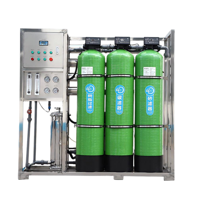
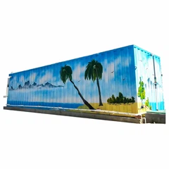
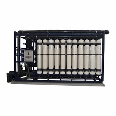

A Pressurized Ultrafiltration (UF) Membrane Water Purification System uses pressure-driven hollow-fiber membranes to eliminate suspended solids, colloids, turbidity, bacteria, and protozoa. Providing a reliable physical barrier, these systems protect downstream processes and ensure compliance with strict discharge or potable water standards.
UF operates via size exclusion in the 0.01 to 0.1 micron pore size range. It is purely a physical separation process. It does not remove dissolved salts or Total Dissolved Solids (TDS) and should not be used as a primary desalination technology.
Technical Specifications Matrix
A UF system should not be selected based on flow rate alone. Evaluate the following engineering parameters together during procurement review.
|
Parameter |
Technical Consideration |
Standard Design / Reference Range |
|
Feed-Water Source |
Dictates pretreatment and material selection |
Surface water, well water, industrial effluent, tertiary wastewater |
|
Membrane Material |
Determines chemical tolerance, mechanical strength, and lifespan |
PVDF (Polyvinylidene Fluoride), PES (Polyethersulfone), or PVC |
|
Membrane Configuration |
Governs flow dynamics and solids tolerance |
Hollow fiber (Out-to-In or In-to-Out flow path) |
|
Nominal Pore Size |
Defines particulate retention threshold |
0.01 - 0.04 microns |
|
Design Permeate Flux |
Dictates total required membrane area |
40 - 100 LMH (L/m2*h) based on feed quality |
|
Operating TMP |
Measures hydraulic driving pressure across the membrane |
Normal: 0.3 - 1.5 bar (4.35 - 21.75 psi); Max: 2.5 bar |
|
System Recovery |
Ratio of product water to total feed water |
85% - 95% (application dependent) |
|
Permeate Turbidity |
Measures physical filtration efficiency |
Less than 0.1 NTU (typically over 99% reduction) |
|
Silt Density Index (SDI15) |
Crucial indicator for Reverse Osmosis (RO) pretreatment |
SDI15 less than or equal to 2.0 (guaranteed under 3.0) |
|
Pathogen Removal |
Biological barrier performance |
4-log (99.99%) retention of bacteria and protozoa |
|
pH Tolerance Range |
Governs cleaning chemical options and feed limits |
Continuous: 2 - 11; Cleaning (CIP): 1 - 12 |
|
Operating Temperature |
Influences fluid viscosity and membrane flux |
5 to 40 degrees C (41 to 104 degrees F) |
|
Backwash Frequency |
Hydraulic cleaning interval to restore operating TMP |
Every 20 - 60 minutes (30 - 60 seconds duration) |
|
CEB Frequency |
Chemically Enhanced Backwash for organic/biological control |
Daily to weekly (using NaOCl, HCl, NaOH, or Citric Acid) |
|
CIP Requirements |
Intensive chemical cleaning for persistent fouling |
Every 1 to 6 months based on permeability decline |
|
Automation Level |
Controls operational oversight and system protection |
Fully automated PLC control with HMI (Siemens / Allen-Bradley) |
Technology Selection: Is Pressurized UF the Right Choice?
Target Contaminants Removed
Suspended solids and Total Suspended Solids (TSS)
Colloidal silica and fine particulate matter
Turbidity and micro-plastics
Bacteria, protozoan cysts (Cryptosporidium, Giardia), and viruses (partial)
High-molecular-weight organic matter
Technology Boundaries
UF is not a universal substitute for Reverse Osmosis (RO), Nanofiltration (NF), Microfiltration (MF), conventional clarification, or biological treatment.
• Pressurized UF vs. RO: UF removes particulates without altering dissolved ions. RO is required when significant dissolved salt, conductivity, or TDS reduction is needed.
• Pressurized UF vs. NF: NF is selected when target contaminants include multivalent ions, hardness (Ca2+, Mg2+), or low-molecular-weight organic molecules.
• Pressurized UF vs. MBR: Membrane Bioreactors (MBR) combine biological activated sludge degradation with membrane separation, primarily designed for raw municipal or high-BOD industrial wastewater treatment.
Typical Industrial and Municipal Applications
Surface Water & Drinking Water Treatment: Provides a physical barrier for river, lake, and reservoir sources. Maintains permeate turbidity below 0.1 NTU despite seasonal feed fluctuations in turbidity, algae, and organic loading.
Reverse Osmosis (RO) Pretreatment: Installed upstream of brackish or seawater RO systems to protect membranes from particulate fouling, extending element lifespan by guaranteeing an SDI15 of less than 2.0.
Industrial Process Water: Delivers process water for electronics manufacturing, pharmaceutical formulation, food and beverage processing, power generation boiler feed, and chemical manufacturing.
Tertiary Wastewater Treatment & Water Reuse: Positioned downstream of biological secondary clarifiers to polish industrial effluent or municipal wastewater for cooling tower makeup, irrigation, or plant recycling.
Manufacturing Quality Control & International Compliance
System performance relies on skid fabrication quality, automated control integration, and strict quality verification.
International Standards & Certifications
• Drinking Water Safety: NSF/ANSI 61 and NSF/ANSI 419 certified membrane components.
• Quality Management: Manufactured under ISO 9001, ISO 14001, and ISO 45001 certified facilities.
• Pressure & Electrical Safety: Piping and pressure components engineered to ASME Section VIII / PED 2014/68/EU standards; electrical control panels carry CE or UL 508A markings.
Factory Acceptance Testing (FAT) Checkpoints
• Component Inspection: Verification of PVDF/PES membrane modules, feed pumps, automated valves, and instruments against approved submittals.
• Hydrostatic Testing: Structural integrity checks and hydrostatic pressure testing at 1.5 times the design operating pressure.
• Electrical & Logic Testing: Point-to-point I/O checks, fault alarm simulation, and automated valve sequence validation (Filtration -> Hydraulic Backwash -> Air Scour -> CEB -> CIP).
Technical Documentation Provided for Review
Every system is supported by an engineering documentation package:
Process Flow Diagrams (PFD) and Piping & Instrumentation Diagrams (P&ID).
3D CAD models and 2D General Arrangement (GA) drawings with footprint layouts.
Complete Equipment, Valve, and Instrument Lists with sub-supplier details.
Electrical Schematic Drawings, Panel Layouts, and Control Logic Philosophy.
Detailed Operation & Maintenance (O&M) manuals and 2-Year Recommended Spare Parts List.
Factory Acceptance Test (FAT) reports, material mill certificates, and calibration records.
Information Required for a Detailed Technical Quotation
To receive a tailored proposal, please provide the following details when submitting an inquiry:
Feed-Water Analysis: Water source, turbidity (NTU), TSS (mg/L), temperature range, pH range, TOC/COD, oil & grease levels, and iron/manganese concentrations.
Capacity Requirements: Net permeate flow rate (m3/h or GPM), daily volume (m3/day), and operating hours per day.
Target Water Quality: Destination requirements (potable water standard, RO feed SDI less than 2, industrial process specification).
Site & Utility Conditions: Indoor/outdoor installation, footprint constraints, electrical supply (Voltage/Hz/Phase), and available compressed air or chemical supply.
FAQ
Q: What is the main operational difference between Pressurized UF and Submerged UF systems?
A: Pressurized UF modules house membrane fibers inside sealed pressure vessels, utilizing dedicated pumps to push water through the membrane at operating pressures up to 1.5 - 2.5 bar.
Q: How frequently do UF membrane modules need to be replaced?
A: With proper feed pretreatment, regular hydraulic backwashing, and automated CEB/CIP maintenance, industrial PVDF pressurized UF membranes typically have an operational lifespan of 5 to 7 years.
Q: Why is UF preferred over conventional sand or multi-media filters for RO pretreatment?
A: UF provides an absolute physical barrier with a fixed pore size (0.01 - 0.04 microns), ensuring consistent permeate quality (SDI15 less than 2.0, Turbidity less than 0.1 NTU) regardless of feed water turbidity spikes.
Q: What chemical agents are used for CEB and CIP processes?
A: Chemical selection depends on the foulant type. Inorganic scaling (calcium carbonates, iron oxides) is removed using acidic solutions like Citric Acid or Hydrochloric Acid (HCl).
Q: How much wastewater does a Pressurized UF system generate?
A: Pressurized UF systems achieve high recovery rates, typically between 85% and 95%. The remaining 5% to 15% of water is used for hydraulic backwashing, air scouring, and chemical cleaning flushes to keep the membrane surface clear.
Hot Tags: pressurized uf membrane water purification system, China pressurized uf membrane water purification system manufacturers, suppliers, factory, Parallel Plate Clarifier Unit