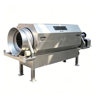
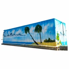
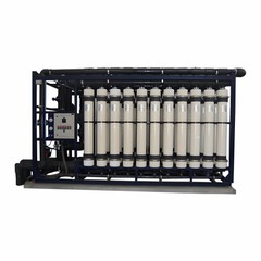

A Containerized DAF Wastewater Treatment Unit combines dissolved air flotation equipment, process piping, pumps, controls, and selected auxiliary systems into a factory-assembled, modular treatment package.
Typical Target Industries
|
Industry Sector |
Primary Wastewater Contaminants |
|
Food & Beverage Processing |
Organic suspended solids, fats, oils, washdown organics |
|
Meat & Poultry Processing |
High FOG, proteins, blood, fine suspended organics |
|
Dairy Production |
Milk fats, proteins, CIP cleaning chemicals, variable pH loads |
|
Seafood Processing |
Suspended organic matter, fish oils, proteins |
|
Oil & Petrochemical |
Free oil, dispersed oil, emulsified hydrocarbons, fine solids |
|
Chemical Manufacturing |
Precipitated chemical flocs, suspended solids, insoluble organics |
|
Pulp & Paper |
Wood fibers, suspended solids, organic loading |
|
Textiles & Dyeing |
Color flocs, suspended solids, chemical residues |
Key Design Parameters
Hydraulic Loading
Average flow rate (m3/h)
Peak flow rate (m3/h)
Daily wastewater volume (m3/day)
Daily operating hours and batch discharge schedules
Pollutant Loading
TSS (mg/L)
COD and BOD (mg/L) - DAF removes particulate and insoluble COD/BOD. Dissolved organic COD requires downstream biological or chemical treatment.
Oil and Grease / FOG (mg/L)
pH, conductivity, and operating temperature
Chloride and salinity levels (dictates material selection)
Effluent Quality & Downstream Limits
Defining target discharge or reuse parameters determines the required saturation ratio, surface loading rate, and chemical pre-treatment design.
Chemical Conditioning Requirements
Most industrial DAF applications require chemical dosing to break emulsions and build floatable flocs:
pH adjustment (acids/caustics)
Coagulation (PAC, Ferric Chloride, Alum)
Flocculation (Anionic or Cationic Polymers)
Sludge Management
DAF concentrates separated pollutants into a floating sludge blanket (typically 2% to 6% dry solids). Project planning must account for daily sludge volume, transfer pumps, temporary storage, and dewatering equipment (e.g., screw press or filter press).
Technical Specifications & Scope of Supply
|
Category |
Component Scope & Technical Details |
|
DAF Flotation Tank |
Separation vessel (Coated Carbon Steel, SS304, or SS316), microbubble distribution manifold, automatic mechanical surface skimmer, bottom sediment scraper, and drain valve. |
|
Air Saturation System |
High-efficiency air dissolution vessel or multiphase saturation pump, air compressor connection, microbubble release valves generating 10 to 30 micron bubbles. |
|
Chemical Dosing Module |
Pipe flocculator or reaction tanks with mixers, automated dosing pumps (pH, coagulant, polymer), polymer preparation unit, inline pH/ORP monitoring. |
|
Pumps & Piping |
Heavy-duty feed and recycle pumps, internal process piping (SS304, SS316, or UPVC), automated control valves, and sampling ports. |
|
Instrumentation & Controls |
Flow meters, level transmitters, pressure gauges, IP55/IP65 control panel, Siemens or Schneider PLC with colored HMI touchscreen interface. |
|
Container Enclosure |
Standard 20ft, 40ft, or 40ft HQ ISO container, structural skid reinforcement, non-slip floor, internal LED lighting, ventilation fan, access doors, and drainage sumps. |
Treatment Process Overview
Wastewater Feed: Equalized raw wastewater is pumped into the treatment module at a controlled flow rate.
Chemical Reaction: Coagulants and polymers are injected into an inline pipe flocculator or mixing tank to destabilize particles and form flocs.
Dissolved Air Injection: A portion of clarified effluent (15% to 30%) is pressurized and saturated with air, then injected into the DAF contact zone.
Flotation: Microbubbles (10 to 30 microns) attach to flocs, causing them to float to the liquid surface.
Sludge Removal: The surface skimmer sweeps the floating sludge into a collection hopper while settled solids are periodically flushed from the bottom sump.
Clarified Water Outlet: Clarified water overflows an adjustable weir for discharge, reuse, or downstream biological treatment.
Battery Limits & Site Responsibilities
|
Factory Scope (Vendor Responsibility) |
Site Scope (Buyer Responsibility) |
|
Mechanical assembly & skid mounting inside container |
Concrete pad or foundation preparation |
|
Internal piping, valving, and wiring connections |
External piping hookups (Influent, Effluent, Sludge) |
|
Control panel assembly, PLC programming, and HMI setup |
Main incoming power connection to control cabinet |
|
Pre-shipment hydro-testing and dry functional runs |
Initial chemical supply and storage tanks |
|
Internal container lighting, ventilation, and sumps |
Compressed air and utility water supply hookups |
|
Factory Acceptance Testing (FAT) |
Site positioning, field cabling, and final commissioning |
Engineering & Quality Assurance
Maintenance Access & Layout Design
System layouts are engineered using 3D CAD modeling to ensure compact footprints without hindering maintenance:
Direct access to pump seals, drive motors, and skimmer mechanisms
Clear sightlines and calibration access for instruments and sensors
Sufficient door clearance for chemical drum replacement and major servicing
Materials of Construction
Wetted components are matched to wastewater chemistry:
• Coated Carbon Steel: Epoxy-coated for neutral, non-corrosive industrial wastewater.
• Stainless Steel 304: Standard for food, beverage, dairy, and municipal applications.
• Stainless Steel 316 / 316L: Specified for high-chloride, acidic, or high-salinity industrial fluids.
International Standards & Testing
Systems are manufactured under ISO 9001 quality frameworks with optional CE mark compliance and ASME/EN vessel standards. Factory Acceptance Testing (FAT) includes dimensional checks, hydrostatic pressure tests, electrical continuity checks, and clean-water functional runs prior to dispatch.
Case Highlights
Poultry Processing Plant (Southeast Asia): Supplied a 40ft High-Cube containerized DAF system (60 m3/h). Achieved over 92% TSS removal and reduced FOG from 1,200 mg/L to under 50 mg/L prior to biological treatment.
Dairy Processing Plant (Middle East): Delivered an integrated 20ft containerized DAF with automated dosing (25 m3/h), effectively handling organic load surges from daily CIP washdowns.
FAQ
Q: Can a containerized DAF system treat dissolved COD and BOD?
A: DAF removes particulate and insoluble COD/BOD associated with suspended solids, fats, and oils. Dissolved COD and BOD pass through flotation and require downstream biological treatment or advanced oxidation.
Q: How are containerized DAF units transported globally?
A: Systems built inside standard 20ft, 40ft, or 40ft High-Cube ISO containers are shipped via standard ocean container vessels. Custom skid systems are shipped using flat-rack or open-top containers.
Q: Is chemical dosing mandatory for DAF operation?
A: While free oils and large floatable solids can separate naturally, most industrial applications require coagulation and polymer dosing to form stable flocs and achieve clarification efficiency above 90%.
Q: Can the container enclosure be insulated for extreme climates?
A: Yes. Containers can be equipped with thermal insulation, internal HVAC systems, anti-condensation coatings, or explosion-proof electrical components for desert, sub-zero, or hazardous environments.
Q: What testing is completed before shipment?
A: Factory Acceptance Testing (FAT) includes hydrostatic vessel testing, mechanical operational checks, electrical panel testing, instrument signal verification, and clean-water functional runs. Third-party inspection (e.g., SGS, TUV) can be arranged prior to container sealing.
Hot Tags: containerized daf wastewater treatment unit, China containerized daf wastewater treatment unit manufacturers, suppliers, factory, Skid-Mounted Heavy-Duty Effluent Plant